


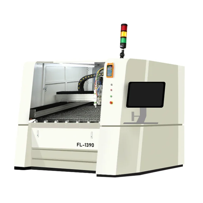
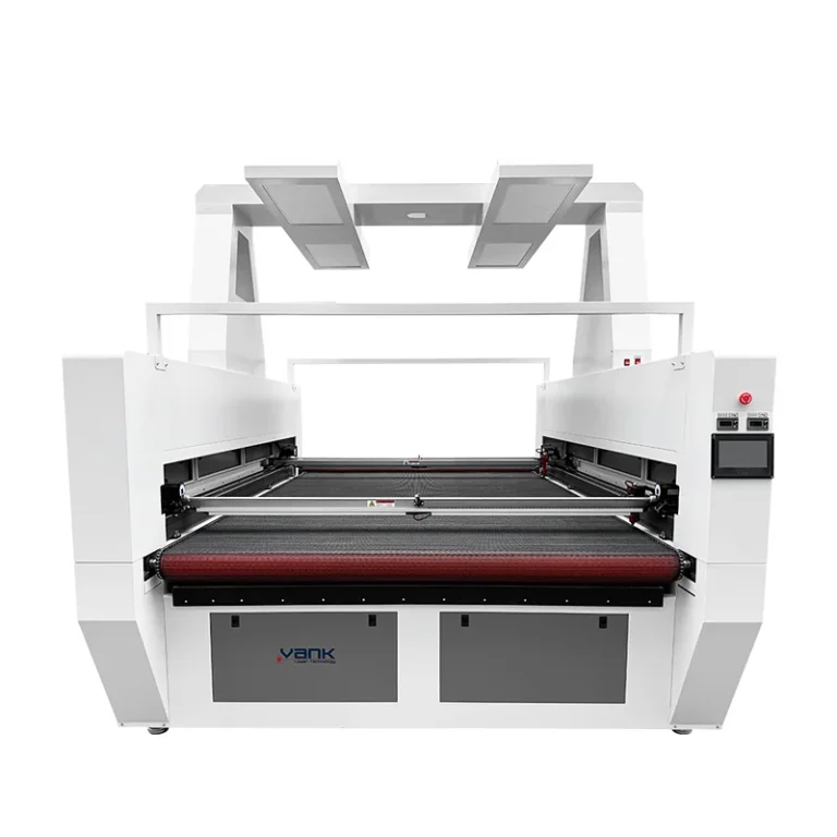
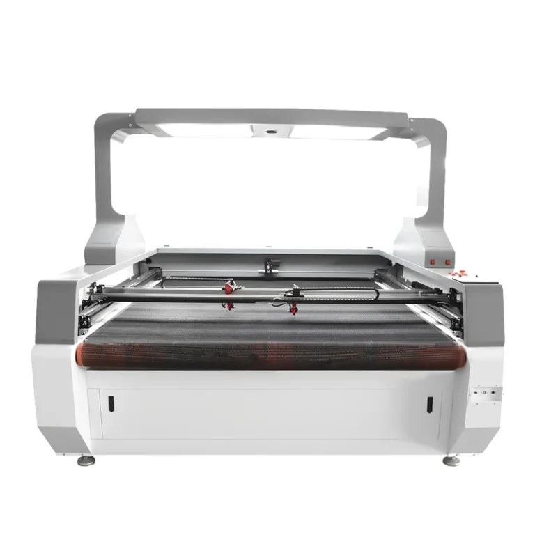
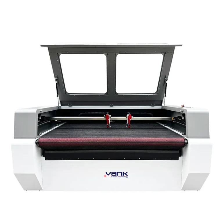
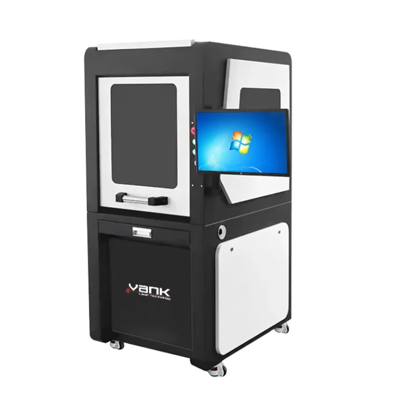
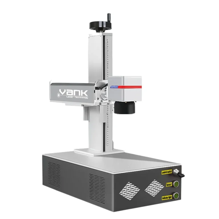
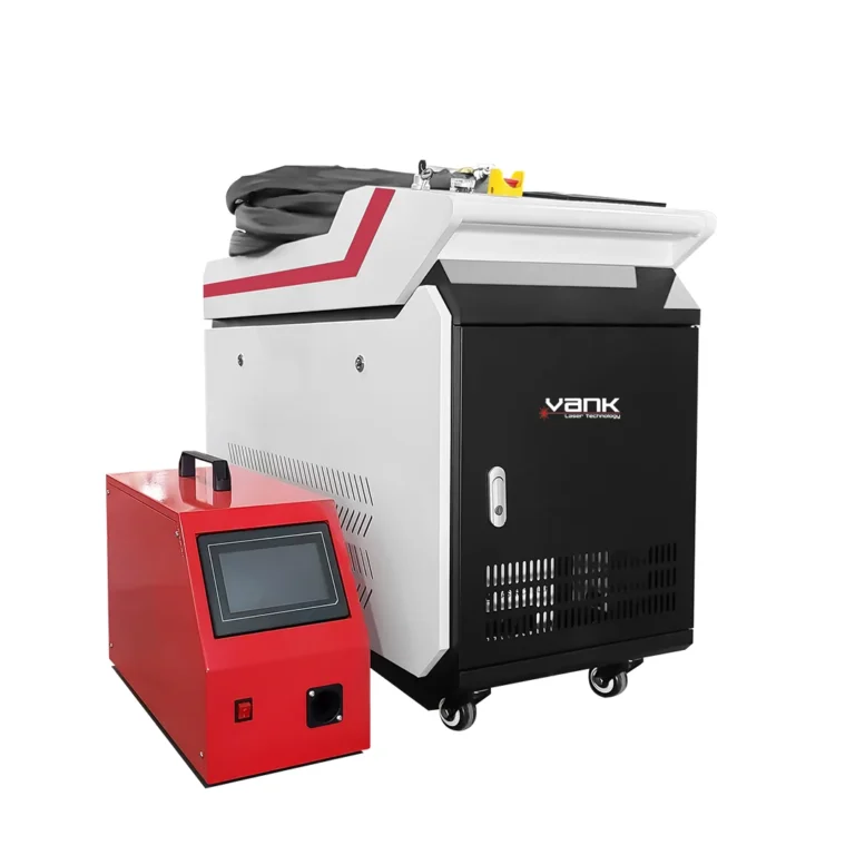
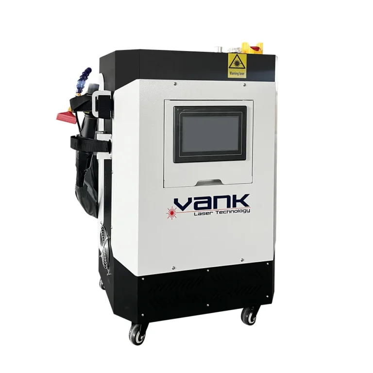
A CO2 laser machine should be configured from the application backward, not chosen by model name or rated wattage alone. The usable work envelope, material approval, process result, motion system, table, extraction, cooling, controller and safety package must work as one system.
A flatbed acrylic cutter, a vision-guided printed-fabric cutter and a roll-fed textile system can share the same laser category while requiring very different hardware. A useful quotation therefore needs a defined bill of materials, utilities, scope of supply and acceptance method.
Use this guide to compare quotations line by line and convert sample-cut results into a purchase specification for a CO2 laser machine.
Why the Complete Configuration Matters
Two machines with similar cabinets and nominal power can deliver different results because the laser source, optics, motion components, usable bed, controller, cooling and fume-control systems are different. Options also change loading, registration, cycle time and maintenance.
Before comparing prices, define these production facts:
- Largest part and raw-stock dimensions, including margins and clamping area;
- Sheet, panel or roll format, plus roll width, diameter and weight where applicable;
- Cutting, engraving, perforating or registered contour cutting, with priority stated;
- Blank material, printed contour, fiducial marks or natural-feature recognition;
- Target pieces per shift, batch size, changeover frequency and acceptable cycle time;
- Exact material trade name, composition, thickness range and supplier safety data sheet.
These inputs let the supplier issue a configuration-controlled quotation instead of an incomplete base-machine price.
1. Specify Laser Performance with Process Evidence
Rated power is only one variable. Tube technology, beam quality, power stability, spot behavior, optics, motion tuning and cooling all affect the result. Fine engraving may favor controllable low-power output, while production cutting must be proven at the required thickness and speed.
Ask the supplier to document four items for every critical material:
| Process Evidence | What the Supplier Must Record |
|---|---|
| Cutting result | Material, thickness, speed, passes, edge quality, kerf and accepted cycle time |
| Engraving result | Artwork, resolution, depth or contrast target, speed and consistency across the bed |
| Laser source | Technology, manufacturer, model, rated power, warranty and matched chiller |
| Production margin | Continuous-run duration, duty cycle, reject criteria and repeatability evidence |
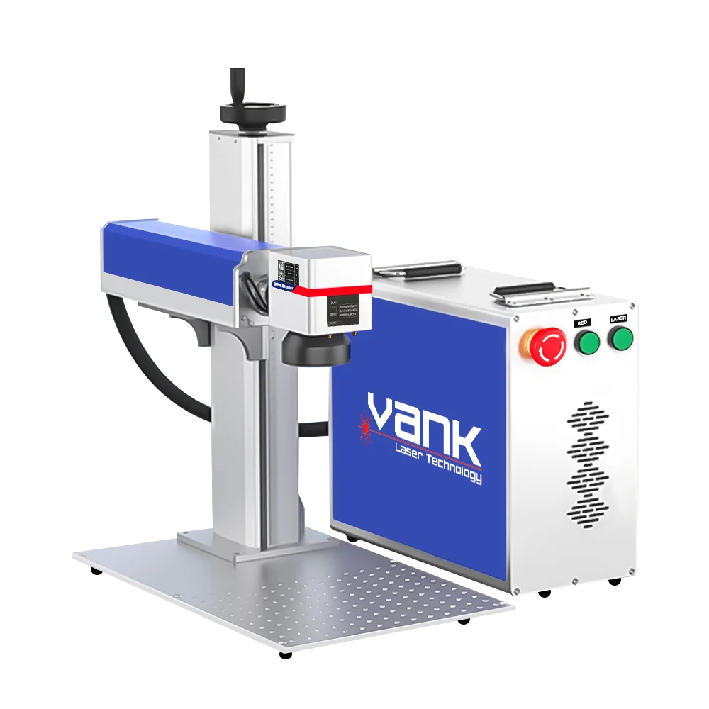
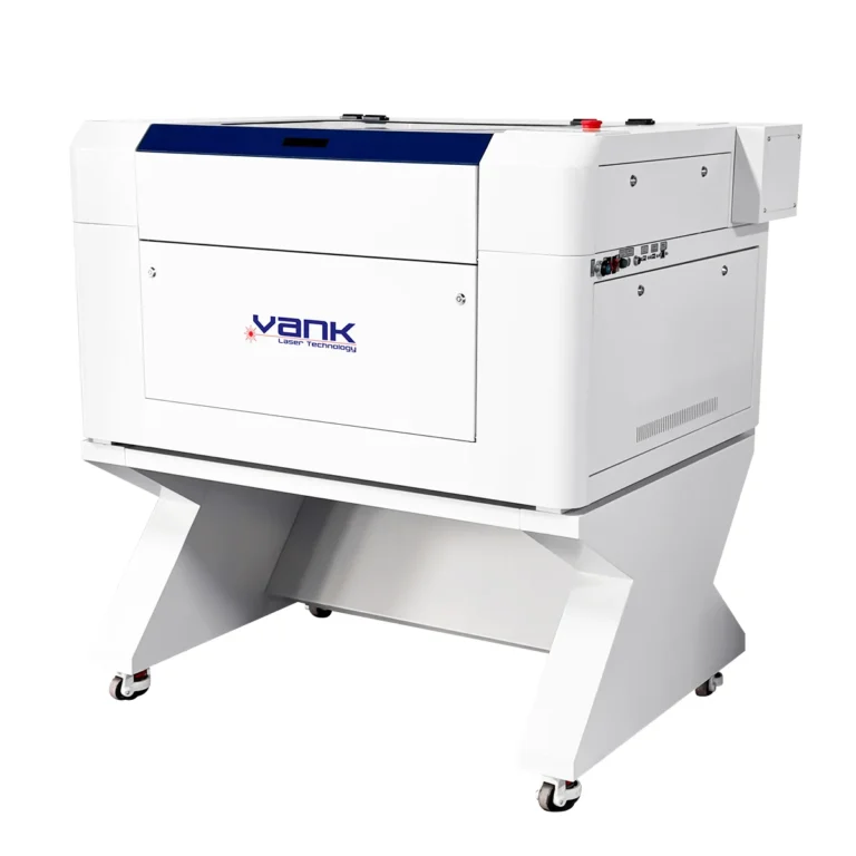
Use the High Speed CO2 Laser Engraving Cutting Machine as a compact-platform reference, then confirm the quoted laser source, usable area and performance with your own files and materials.
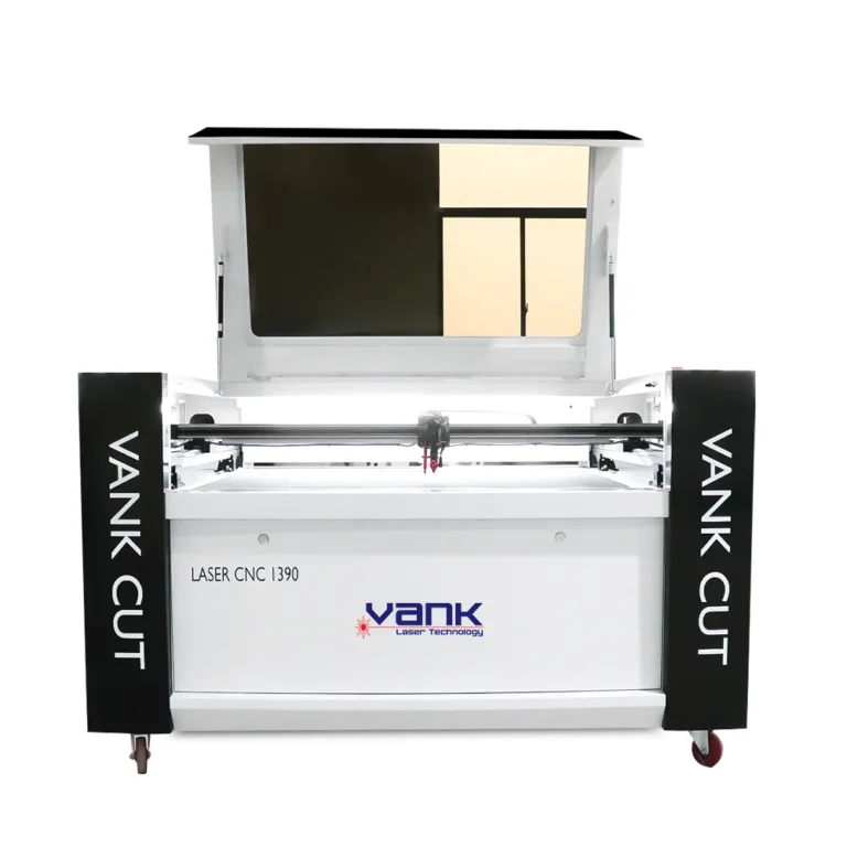
Use the 1490 CO2 Laser Engraving Cutting Machine as a general flatbed reference. Treat listed options as a starting point; the signed quotation should identify the exact source, controller, table, cooling and included accessories.
For a larger bed or higher-throughput process, compare the 1490, 1610 and 1325 platform directions only after a sample test establishes the required power, speed, edge quality and repeatability.
2. Define the Usable Work Envelope
Advertised table size is not always the same as the usable processing area. Confirm X/Y travel, maximum part size, pass-through limits, loading clearance, focus range and any area lost to camera calibration, fixtures or dual heads.
Choose the platform from the largest approved stock and part, then verify these points:
| Platform Check | Required Confirmation |
|---|---|
| Usable X/Y area | Maximum travel and processing area after fixtures, camera or multiple heads |
| Raw-stock fit | Loading opening, pass-through limits, margins and support for the largest stock |
| Part and nesting | Largest part, origin strategy, spacing and production nesting file |
| Machine footprint | Overall dimensions, service clearance, door route and floor-loading requirement |
| Focus and Z clearance | Material-height range, focus method, bed flatness and fixture allowance |
| Roll-media envelope | Usable width, feeder limits, index length, tracking and conveyor integration |
The 1490 CO2 laser machine can be used as a platform reference, but every quotation should state the exact usable X/Y envelope and external footprint instead of relying on a model number.
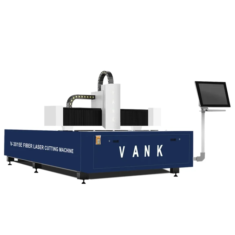
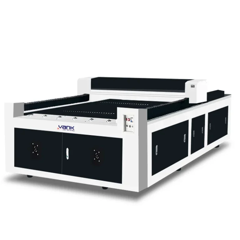
For large sheet work, compare the CO2 laser machines for advertising and retain the category overview as a routing reference. Confirm loading access, floor space, extraction route and shipping dimensions for the selected model.
3. Match the Support Bed to the Material
The support surface influences flatness, back reflections, underside marks, smoke flow, small-part retention and cleaning time. Specify the table by actual material behavior rather than accepting it as a generic accessory.
Honeycomb Bed
A honeycomb bed gives broad support to thin sheets and small parts. It can be useful for paper, card and some flexible stock, but resin and debris accumulation must be controlled and underside marking should be checked on representative samples.
Lamella or Knife-Blade Bed
A lamella bed reduces the contact area under rigid sheets such as acrylic, wood and approved panels. Confirm blade spacing, replaceability, flatness and the underside finish obtained on the actual part.
Conveyor Bed
A conveyor is intended for approved roll media. Confirm belt material, usable width, tracking, tension control, indexing repeatability and the way fumes and offcuts are managed. Do not specify synthetic media until its composition and laser suitability are known.
Where sheet types vary, document each included bed and the changeover method. Options shown for the 1490 platform should still be identified explicitly in the final bill of materials.
4. Add Vision Only for a Defined Registration Task
A camera should solve a measurable positioning problem. Define whether the system must detect fiducial marks, printed contours, multiple parts, natural edges or a full-field layout, and specify the required registration accuracy over the usable area.
A vision test should cover:
- The production artwork, print method and real fiducial design;
- Expected print stretch, shrinkage and distortion;
- The complete calibrated camera field and any stitching zones;
- Lighting changes caused by glossy, dark or reflective surfaces;
- Part rotation, spacing and nesting representative of production;
- Approved material samples with actual print contrast;
- Measured contour error at the center and edges of the bed;
- A repeatability run with an agreed number of consecutive parts.
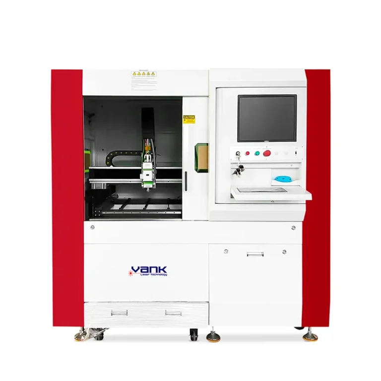
The CO2 Laser Cutting Machine with CCD Camera Visual is the relevant product direction for registered cutting. Confirm the camera type, calibration method, software workflow, field coverage and measured acceptance result in writing.
For unprinted sheets and standard vector jobs, a camera may add cost and setup without improving the result. Approve it only after a representative registration test.
5. Specify Roll Feeding as a Complete System
Automatic feeding is a production system, not simply an add-on table. It must handle the supplied roll without skew, uncontrolled tension, wrinkles or registration drift.
A roll-feed specification should include:
- Maximum and minimum roll width, diameter, core size and weight;
- Exact approved material composition, thickness and stretch behavior;
- Required index length and whether parts exceed one bed length;
- Unwinding, edge guiding, tension control and take-up requirements;
- Target indexing accuracy and cycle time under production load;
- Vision registration, nesting and compensation requirements where printed media is used.
Use a fixed bed for sheets and discrete panels when continuous transport is unnecessary. Use a conveyor only after feeding and cutting are demonstrated together with the actual roll.
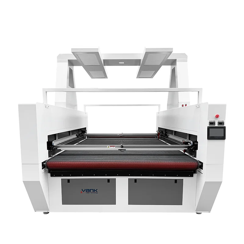
The CO2 Laser Fabric Cutter with Auto Feeding and Vision Camera is the relevant direction for roll-based work. The quotation should identify the feeder, conveyor, usable width, camera workflow and accepted roll specification.
6. Validate Dual-Head Production Before Ordering
Two heads can reduce cycle time only when part geometry, spacing and motion strategy allow both heads to work productively. A second head can also reduce the usable envelope or add collision and setup constraints.
Request a dual-head study that confirms:
- The production nesting and repeated pattern used for the test;
- Minimum and maximum head spacing across the usable bed;
- Independent or synchronized motion behavior and parameter control;
- Collision limits, exclusion zones and safe homing behavior;
- Measured cycle time and accepted-part output versus one head.
A single-head configuration is usually easier to justify when:
- Jobs and layouts change frequently;
- Parts are irregular or cannot be paired efficiently;
- The system is used mainly for sampling and short runs;
- Fine engraving consistency matters more than parallel throughput;
- Head spacing would waste material or restrict usable travel.
Approve dual heads from a timed demonstration using representative nesting. Record the tested source power, head spacing, parameters and accepted output in the FAT document.
7. Engineer Cooling, Extraction and Air Assist
Cooling, fume extraction and air assist are process-critical subsystems. Their capacities and alarms should be part of the quotation and factory acceptance test, not left as unspecified accessories.
Cooling System
Match the chiller to the exact laser source and duty cycle. Specify coolant type and quality, operating temperature range, flow and temperature alarms, ambient limits, condensation controls, hose connections and whether the chiller interlocks the laser.
Fume Extraction
Size extraction from the approved material, table volume, duct length, bends, pressure loss and local discharge or filtration rules. Require accessible cleaning points and confirm that airflow is sufficient across the working area during the sample process.
Air Assist
Specify clean, dry and oil-free air, pressure and flow at the nozzle, nozzle size and compressor or pump scope. Validate the setting for edge quality, lens protection and ignition control on each approved material.
Compare quotations against a scope list covering chiller, extractor, fan, filters, duct adapters, air source, regulator, hoses and electrical connections. Exclusions should be stated clearly.
8. Confirm Controller and Software Compatibility
Record the exact controller model, firmware, licensed software and supported operating system. General statements such as “DSP control” or “LightBurn compatible” are not enough for workflow acceptance.
The software review should verify:
- Exact controller brand, model, firmware and communication ports;
- Imported vector and bitmap formats tested with the buyer’s files;
- Licensed software version and confirmed LightBurn device support where required;
- Online and offline job transfer, storage limits and recovery behavior;
- Available interface languages and operator permission controls;
- Layer, speed, power, origin, array and nesting controls used in production;
- Parameter backup, calibration backup and restore procedure;
- Operator training, remote-support method and service access requirements.
If a Ruida-based 1490 configuration is quoted, verify the exact controller against the current LightBurn supported-device documentation and include the correct license in the bill of materials.
For a vision system, test the entire path from artwork import and camera calibration to contour generation, output and repeatable cutting. File-format support alone does not prove registration performance.
9. Define Safety, Utilities and Operating Controls
The machine integrator and buyer should complete a documented risk assessment for the installed process. Confirm the delivered laser classification, guarding, interlocks and local electrical and workplace requirements; do not treat a pointer or autofocus feature as a safety control.
The purchase specification should address:
- Accessible emergency stops and a tested stop/reset sequence;
- Guarding, covers and safety interlocks appropriate to the delivered laser class;
- Electrical drawings, rated voltage and frequency, grounding and isolator requirements;
- Water-flow, over-temperature and other source-protection interlocks;
- Extraction monitoring, approved discharge or filtration and maintenance access;
- Fire detection, supervision, housekeeping and suitable response equipment;
- A written material-approval process using composition data and the supplier safety data sheet;
- Installation checks, operator training, maintenance instructions and lockout procedures.
Exclude PVC and vinyl, PVB, PTFE and other fluorinated or halogenated materials, unknown plastics, and chromium(VI)-containing leather from laser processing unless a qualified safety review explicitly approves the exact material and controls.
Never leave active laser processing unattended. Confirm local fire, fume, electrical and occupational-safety requirements before commissioning the machine.
10. Shortlist a Platform, Then Lock the BOM
Use the following Vank Laser pages to narrow the platform by work envelope, feed method and registration task. Final selection still depends on sample evidence and a signed configuration schedule.
| Configuration Requirement | Product Direction |
|---|---|
| Compact engraving and small-format process testing | High Speed CO2 Laser Engraving Cutting Machine |
| General flatbed cutting and engraving with a configurable support bed | 1490 CO2 Laser Engraving Cutting Machine |
| Medium-format mixed sheet production | 1610 CO2 Laser Engraving Cutting Machine |
| Large advertising sheets, panels and display work | CO2 Laser Machines for Advertising |
| Registered cutting of printed contours or fiducials | CO2 Laser Cutting Machine with CCD Camera Visual |
| Roll-media feeding with vision-guided cutting | CO2 Laser Fabric Cutter with Auto Feeding and Vision Camera |
For every shortlisted machine, request a revision-controlled bill of materials listing brands, model numbers, quantities, included accessories, exclusions, consumables, recommended spares, warranty scope and document package.
11. Information Required for an Accurate Quotation
Send one production brief that every supplier must answer. Consistent inputs make commercial and technical differences visible and reduce assumptions.
| RFQ Input | Information to Provide |
|---|---|
| Material identity | Trade name, supplier, composition, SDS and laser-suitability approval |
| Stock format | Sheet or roll dimensions, thickness range, roll core, diameter and weight |
| Required output | Cut, engrave or register; quality sample; tolerance; target cycle time |
| Artwork | Representative vector, bitmap, nesting and printed-registration files |
| Production demand | Parts per shift, batch size, changeovers, duty cycle and scrap target |
| Platform | Usable envelope, support bed, fixture, loading and roll-feed requirements |
| Utilities and site | Voltage, frequency, air, ambient range, extraction route and floor space |
| Options | Vision, autofocus, rotary, dual heads, feeder and their acceptance criteria |
| Supply scope | Exact BOM, exclusions, consumables, spares, software, training and warranty |
| Delivery and FAT | Destination, packing, documents, sample test and signed acceptance record |
Include material trade name and SDS, composition, thickness range, stock format, maximum part, artwork, quality criteria, output target, utilities, workshop conditions and destination. For printed or roll media, add registration and feed data.
CO2 Laser Configuration FAQ
How should CO2 laser power be specified?
Specify the required result rather than wattage alone: exact material and thickness, cut or engraving quality, speed, duty cycle and acceptance criteria. The supplier should record the tested source and parameters.
Is a higher-power CO2 laser always better?
No. More rated power may improve some cutting processes, but fine control, beam delivery, motion, optics and cooling also matter. Select the lowest validated configuration that meets quality and output requirements with margin.
How do I choose the usable bed size?
Base it on raw stock, the largest part, nesting margins, fixtures and loading method. Confirm usable X/Y travel and external footprint in the quotation because the model name or nominal table can be misleading.
When should I use honeycomb or lamella support?
Use honeycomb when thin stock and small parts need broad support; use lamella or knife blades for many rigid sheets where reduced contact is preferred. Test underside marks, flatness, smoke removal and cleaning on the real material.
When is a camera system justified?
Add vision for a defined registration task such as fiducials or printed contours. Approve it only after measured accuracy and repeatability are demonstrated across the required field with production artwork and material.
When is automatic feeding necessary?
Use it for validated roll-media workflows that require continuous indexing. Specify roll geometry, tension, tracking, indexing repeatability, usable width and integration with vision before acceptance.
Are dual heads necessary for every buyer?
No. They are useful only when nesting and head spacing support parallel work. Compare accepted-part throughput, usable area, setup time and collision constraints against a single-head test.
What must be checked beyond power and table size?
Check the full BOM, usable envelope, source and optics, controller and licenses, cooling, extraction, air assist, safety controls, utilities, commissioning, training, spares, warranty and FAT evidence.
12. Approve the Machine with a Written FAT
Before shipment, run representative jobs with buyer-approved files and materials. Record settings, cycle time, dimensional or registration results, edge and engraving criteria, scrap, alarms, continuous-run duration and accepted-part quantity.
Attach the final BOM, utilities, layouts, manuals, software licenses, backups, spare-parts list, warranty terms and signed FAT record to the order. This turns a broad CO2 laser machine configuration into a verifiable supply contract.