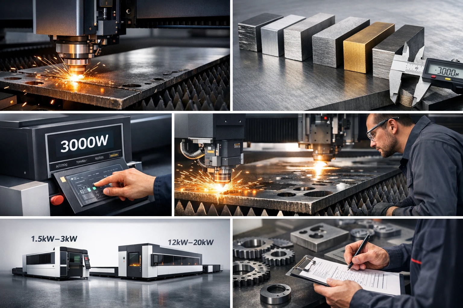



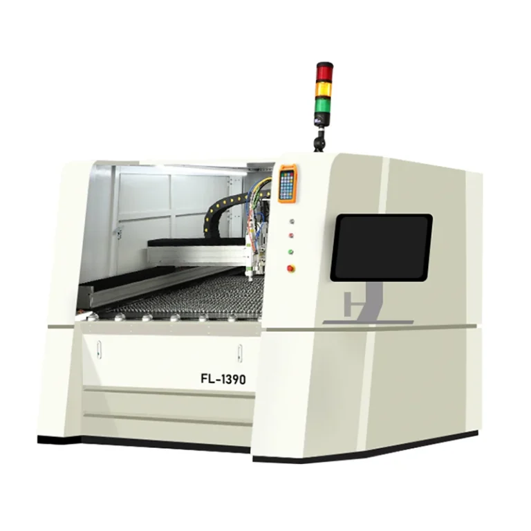
A supplier’s maximum-thickness number is not enough to prove production capability. A useful fiber laser cutting thickness claim must identify the material grade, sheet condition, part geometry, piercing method, assist gas, edge standard, cycle time and exact machine configuration.
Use this guide to build a material-specific test plan. The goal is to verify repeatable, acceptable parts at the required shift output, not simply to separate one sample.
Power remains important, but source mode, beam delivery, cutting head, nozzle, focus control, gas pressure and flow, motion dynamics, nesting and material quality all affect the result.
Build a material-thickness qualification matrix
Start with the orders that consume the most cutting hours, then add peak jobs and credible future demand.
Record:
- exact alloy or grade, finish, coating and protective film
- routine thickness distribution and frequency of peak thicknesses
- part size, holes, contours, tolerances and required edge condition
- target parts per shift, downstream process and allowable rework
This matrix lets every supplier test the same scope. It also prevents an occasional thick job from driving an oversized purchase.
Verify different thickness ranges with different priorities
Thin sheet: qualify detail, dynamics and heat control
For thin sheet, excessive power is not a substitute for stable motion and a controlled process window.
Check:
- small-hole diameter and roundness
- corner quality and fine-contour accuracy
- kerf width, discoloration and heat distortion
- nesting, fly-cut or common-line behavior where applicable
- repeatability across a full nested sheet
The acceptance sample should include the smallest important features and the actual sheet finish used in production.
Medium thickness: qualify process margin and cost per part
Medium-thickness work often requires a balance between edge quality, piercing, speed, gas cost and sufficient process margin.
- compare oxygen, nitrogen or approved air processes by edge requirement
- measure piercing time and restart behavior
- inspect dross, striation, taper and part temperature
- record gas pressure, nozzle and consumption assumptions
Test the production system, including:
- representative nesting and sheet utilization
- loading, unloading and part-sorting time
- chiller, extraction and compressor capacity
- consumables and expected maintenance
- accepted parts per shift and cost per accepted part
A faster straight-line cut does not guarantee a faster completed nest.
Thick plate: qualify piercing, edge quality and duty cycle
A one-off separating cut on thick plate is not a production acceptance test.
Require:
- repeatable piercing on the actual grade and surface condition
- edge roughness, dross, taper and heat-affected appearance within limits
- holes and internal features representative of paid work
- an extended run that demonstrates thermal and process stability
- documented cycle time, gas use, consumables and secondary finishing
Define the approved maximum thickness in the contract with all these conditions attached.
Material and cutting gas change the result
Thickness cannot be evaluated without the material and gas process.
Carbon steel
Oxygen flame cutting adds reaction energy and may support thicker mild-steel processing, but it leaves an oxidized edge. Nitrogen or another approved inert-gas process avoids that oxide layer but requires the laser to provide the cutting energy and can demand higher gas pressure and flow.
Stainless steel
If an oxide-free edge is required for welding, finishing or appearance, qualify nitrogen cutting by dross, discoloration, roughness, gas use and part temperature. Confirm the alloy and surface finish used for the test.
Aluminum, brass and copper
For reflective non-ferrous metals, verify that the exact source, fiber delivery, optics and cutting head are approved for the material and power. Test the actual alloy, surface and film; do not transfer capability from a carbon-steel chart.
The correct configuration must satisfy both the thickness and the material mix.
Use an evidence table instead of a universal thickness chart
A practical comparison table records what each supplier must prove for the quoted machine.
| Material | Routine Thickness | Peak Thickness | Sheet Condition | Gas / Process | Test Geometry | Acceptance Record | Supplier Evidence |
|---|---|---|---|---|---|---|---|
| Carbon Steel | % of cutting hours | frequency required | grade / coating | O2 or approved inert gas | piercing, holes, contours | edge, oxide, dross, cycle | parameters and gas log |
| Stainless Steel | % of cutting hours | frequency required | alloy / finish / film | N2 or approved process | small features and nest | color, dross, roughness | parameters and gas log |
| Aluminum | % of cutting hours | frequency required | alloy / surface / film | approved gas process | holes, edges and restart | dross, taper, dimensions | optical approval and log |
| Brass / Copper | % of cutting hours | frequency required | alloy / surface | approved gas process | piercing and reflection test | edge, pierce, dimensions | source / head approval |
Complete every cell with model-specific test results before treating a thickness claim as an accepted production capability.
This evidence table helps avoid two common mistakes:
- treating a marketing maximum as a repeatable production specification
- comparing different machines under different materials, gases or quality standards
The final comparison should use the same files, materials, gas purity, timing method and acceptance criteria.
Match the working area and handling system
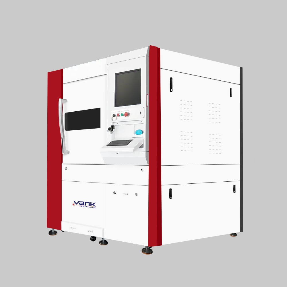
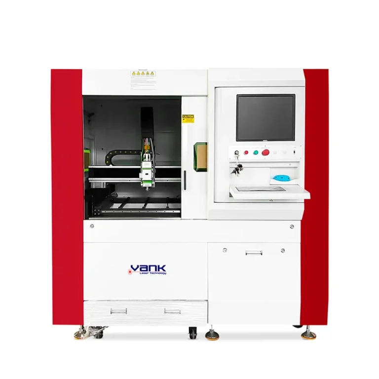
A compact machine can be efficient for:
- small precision parts
- fine details and short nests
- limited sheet formats
- restricted floor space
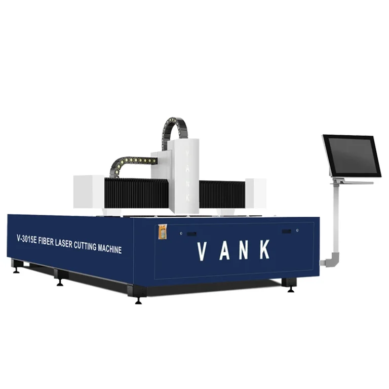
A larger sheet platform may be required for:
- standard 3015 or other full-size stock
- large panels and mixed nests
- exchange tables or automated loading
- higher shift volume with planned unloading
Verify the usable cutting envelope, sheet margins, pallet clearances, material route and installed footprint rather than relying on the nominal table name.
Compare verified cycle time, not feed rate alone
A production trial should record:
- piercing and cutting time for the complete nest
- loading, unloading and part-sorting time
- scrap, rework and accepted-part count
- gas, nozzles, protective optics and other consumables
- restart behavior and stability during an extended run
Calculate accepted parts per shift and total cost per accepted part. A headline feed rate is not enough.
Put supplier support into the acceptance scope
Before payment, confirm:
- sample report and recorded cutting parameters
- exact source, head, controller, chiller and software
- utility list, installation responsibilities and site preparation
- operator and maintenance training
- warranty exclusions, response time and spare-parts availability
- remote support, escalation and service cost
These terms should be written into the quotation, acceptance plan and contract.
Decide from comparable samples and a written FAT
There is no single fiber laser cutting machine that proves every material-thickness combination. Shortlist realistic configurations and test them under equivalent conditions.
Use representative files, actual material, agreed gas, a documented timing method and measurable edge and dimensional criteria. Include routine work, difficult features and at least one peak-thickness job.
Approve the exact bill of materials and factory acceptance test before ordering. The best machine is the one that repeatedly produces acceptable parts at the required cost and shift output.
FAQ
Can one power-to-thickness chart apply to every fiber laser?
No. Source mode, optics, cutting head, nozzle, gas, material grade, surface condition, geometry and quality criteria can change the qualified result. Use model-specific tests.
What proves a maximum-thickness claim?
A repeatable test on the exact material and quoted configuration, with piercing, geometry, edge, cycle time, gas and inspection results documented in the acceptance record.
How should thin-sheet capability be tested?
Use real parts with small holes, corners and fine contours across a nested sheet. Inspect dimensions, kerf, discoloration, heat distortion and repeatability.
How should two machines be compared?
Use the same CAD files, material batch, gas purity, nesting, quality limits and timing method. Compare accepted parts per shift and cost per accepted part.
What should I send before requesting a quotation?
Send the material-grade and thickness matrix, sheet size, representative CAD files, edge and tolerance requirements, target shift output, utilities, automation needs and peak-job frequency.