


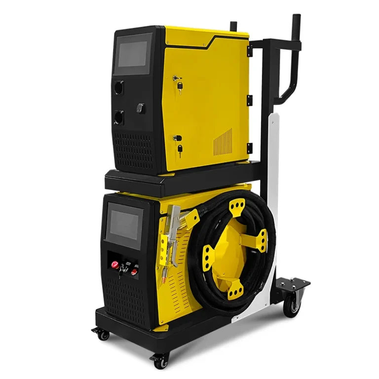
For acrylic display, signage and component production, the useful capacity measure is accepted parts per hour after nesting, loading, cutting, unloading and inspection. A second laser head can increase output only when the repeated layout fits the available head spacing and both process results meet the same quality limits.
A dual-head CO2 laser cutting machine is therefore a production option, not an automatic two-times multiplier. This guide explains how to verify the source architecture, controller support, usable work area, acrylic process window, utilities and factory-acceptance evidence before purchase.
1. Verify the Dual-Head Architecture and Control
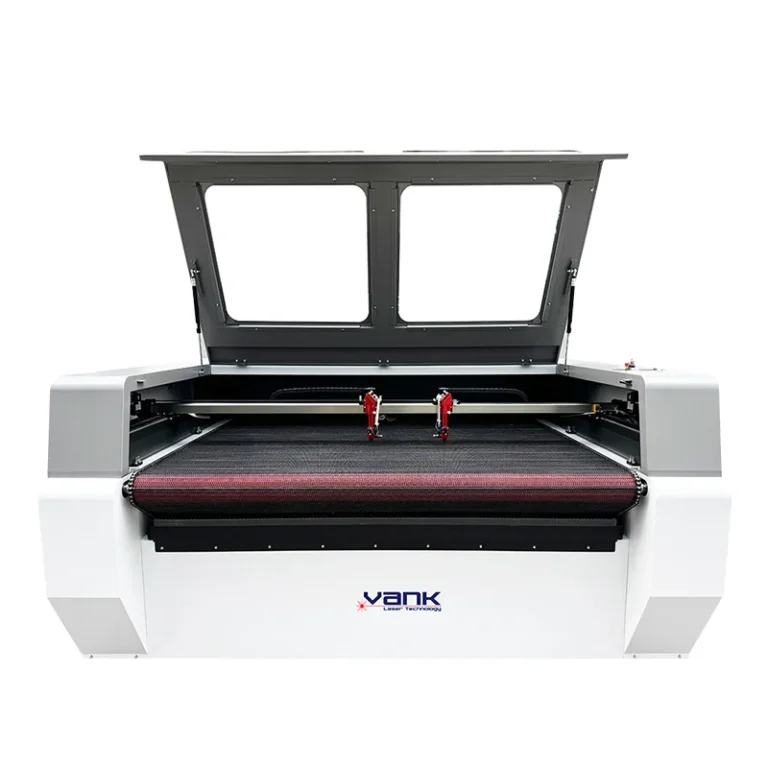
Dual-head CO2 machines may use two sources and two beam paths or another manufacturer-specific arrangement. Ask the supplier to identify the exact architecture, supported operating modes, head offset, collision limits, service procedure and single-head fallback in the signed configuration.
Two Sources, Two Beam Paths and a Shared Gantry
For a two-source system, document two separate CO2 glass laser tubes, the rated output and model of each tube, matched high-voltage supplies, beam-delivery components, cooling circuits, alarms and interlocks:
- Head A: identify its source, power supply, mirror path, lens, nozzle, cooling branch and alarm response.
- Head B: document the same items independently and confirm how its offset and output are calibrated against Head A.
When both heads share an X-axis linear guide, the controller must coordinate motion and the fixed or adjustable offset between heads. Current LightBurn documentation provides Laser 2 controls and a Laser 2 Offset for compatible Ruida hardware, but operation still depends on the machine wiring, controller firmware and manufacturer configuration. Prove the complete workflow with the production file.
2. Specify the Acrylic Process and Complete System
Acrylic results vary by cast or extruded PMMA grade, thickness, pigment, protective film, focal length, optics, air assist, support bed and extraction. Use the table as an RFQ and FAT checklist; do not treat any component model or setting as universal.
| Verification Item | Required Evidence |
| Usable Area and Head Spacing | Measured X/Y travel, fixed or adjustable offset, exclusion zones and single-head travel |
| Laser Sources and Power | Exact two tube models, rated output, matched supplies and model-specific current limits |
| Controller and Software | Controller and firmware, wiring, Laser 2 controls, offset, file test and backup |
| Optics and Focus | Lens and beam path for each head, focus method, adjustment range and repeatability |
| Acrylic Process Window | PMMA grade, film, thickness, edge criteria, kerf, taper, cycle time and accepted yield |
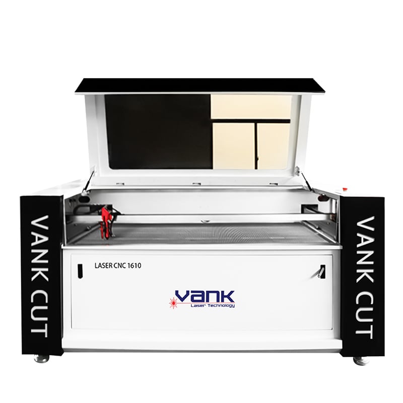
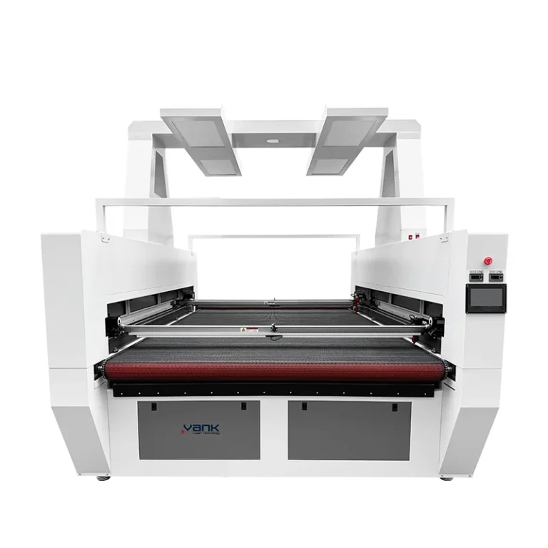
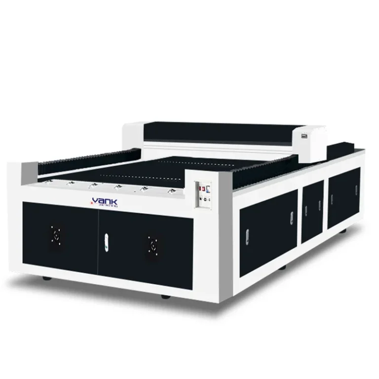
| Cooling and Utilities | Use the 1325 large-platform CO2 laser machine only as a platform reference; size cooling for combined heat load, flow, ambient and duty cycle |
3. Calculate Throughput from Accepted Parts
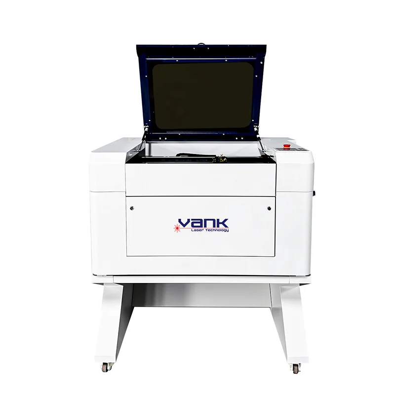
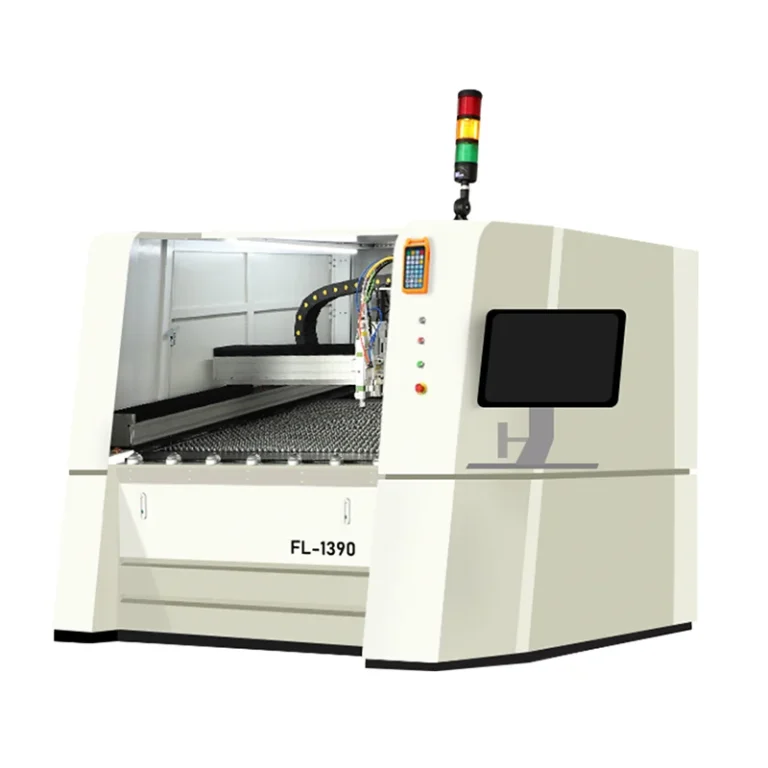
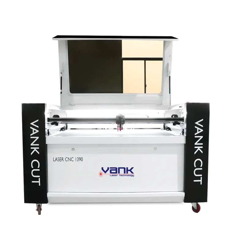
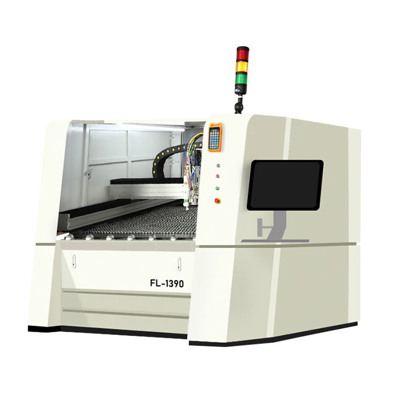
Build the business case with timed trials on the same production file and material. The 1390 full-enclosed thin-sheet laser machine is a separate platform reference; the proposed acrylic system must identify its own CO2 sources, work envelope and dual-head controls.
Choose a representative order that includes the normal part mix, sheet dimensions, routine and peak thickness, required edge quality, tolerances and inspection method. Record the same start and stop points for single-head and dual-head trials.
- Single-head baseline: record nesting yield, setup, beam-on time, handling, inspection, rejects and accepted parts per hour.
- Dual-head trial: repeat the job with the approved offset and operating mode, then record the same metrics. Do not assume a 50% time reduction.
Production evidence: calculate capacity from accepted parts, not theoretical beam-on time. Include nesting yield, head spacing, unusable zones, loading, unloading, cleaning, inspection, rejects, changeover and any time spent repositioning or parking a head.
4. Calibrate Both Optical Paths Safely
A dual-head machine requires two qualified optical paths and a repeatable relationship between the heads. Differences in source output, focus, alignment, lens condition, air assist or extraction can create different kerf, taper, edge finish and dimensions on nominally identical parts.
Step 1: Qualify Beam Delivery and Alignment
Because there are two beam paths, each line needs a documented beam-delivery and alignment verification performed by trained personnel with guarding and interlocks intact.
- Use the manufacturer-approved guarded procedure to verify Head A beam delivery across the usable field; never defeat an interlock or expose personnel to the invisible beam.
- Verify Head B by the same qualified procedure and record any difference in output, kerf, taper, dimensions and edge appearance.
Step 2: Match Focus, Height and Process Results
For acrylic, match the focus condition and resulting process quality of both heads instead of relying on a nominal mechanical dimension alone.
- Measure each head with the manufacturer-approved focus method and confirm that the adjustment range covers sheet flatness, bed variation and the approved thickness range.
- Cut the same test pattern with both heads from one material lot and compare edge gloss, residue, kerf, taper, dimensions and repeatability before release.
5. Decide When Two Heads Add Real Capacity
Dual-head architecture is most useful for standardized batches when two copies or complementary nests fit the verified head spacing and usable area. Typical candidates include repeated acrylic letters, display components, light-guide parts and approved wood products.
Large one-piece jobs, mixed nests or frequent changes may favor a single head. A dual-head machine should run in single-head mode only when the manufacturer documents source isolation, parked-head clearance, usable travel, controller behavior and the approved operating procedure.
Request a Dual-Head Acrylic Production Test
Vank Laser can evaluate a CO2 laser machine configuration using your approved PMMA grade, thickness, sheet size and production files. Request labeled samples, single-head and dual-head time studies, accepted yield, complete BOM, utilities, safety scope, training, warranty, service and written FAT criteria.