


Application and model selection
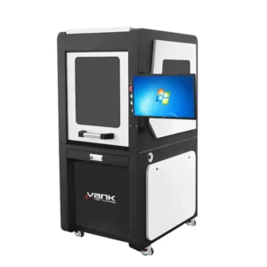
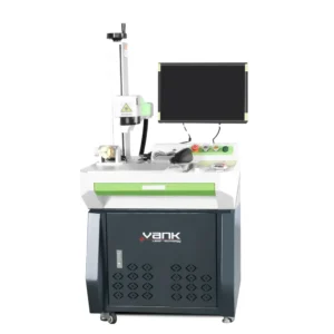
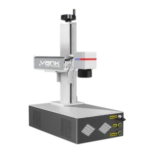
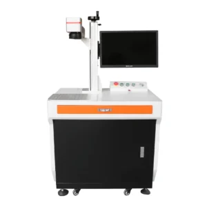
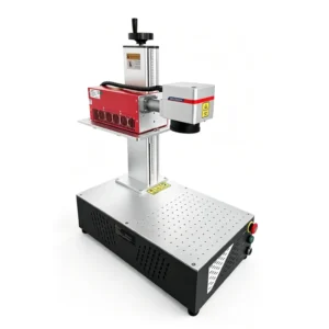
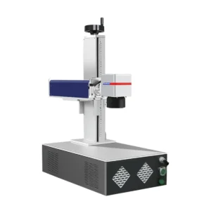
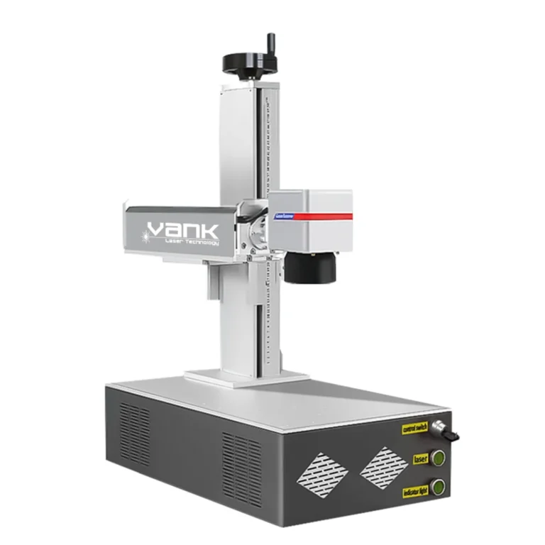
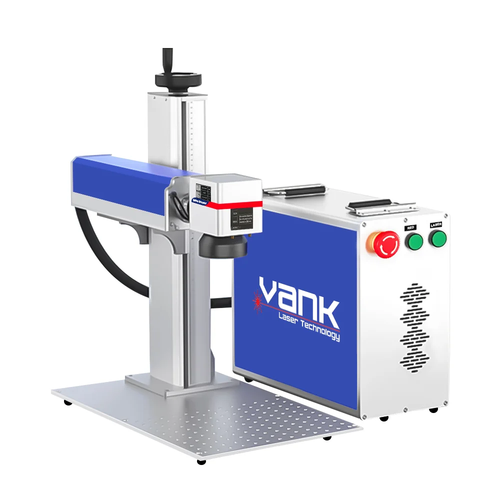
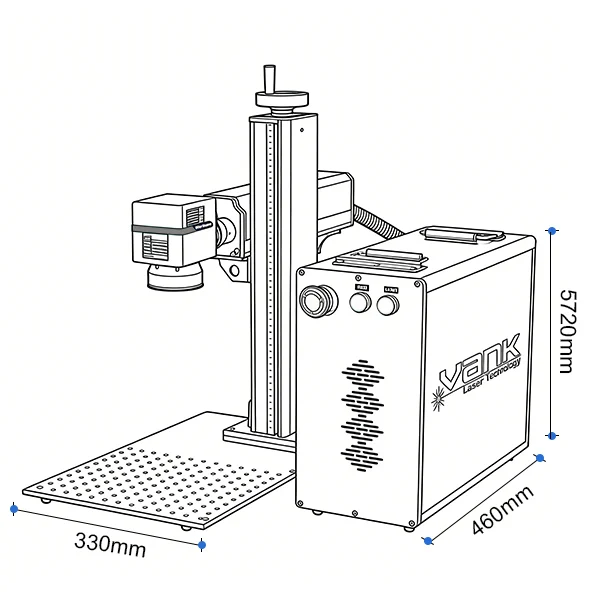
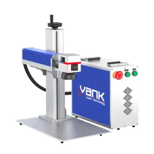
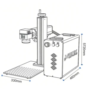
The separate modules help arrange a bench around fixtures and part access. Confirm cable length, bend limits, Z travel and the combined footprint. The marking head remains fixed to its support during normal use; choose the J20H handheld model when the head must be brought to an installed part.
Configuration and specifications
| Parameter | Product configuration |
|---|---|
| Machine format | Split source cabinet and marking column |
| Laser power options | 20 / 30 / 50 / 60 / 70 / 100 W |
| Nominal wavelength | 1064 nm |
| Laser source | 1064 nm Q-switched or MOPA fiber source |
| Marking field | 70 × 70 to 300 × 300 mm; lens and clearance dependent |
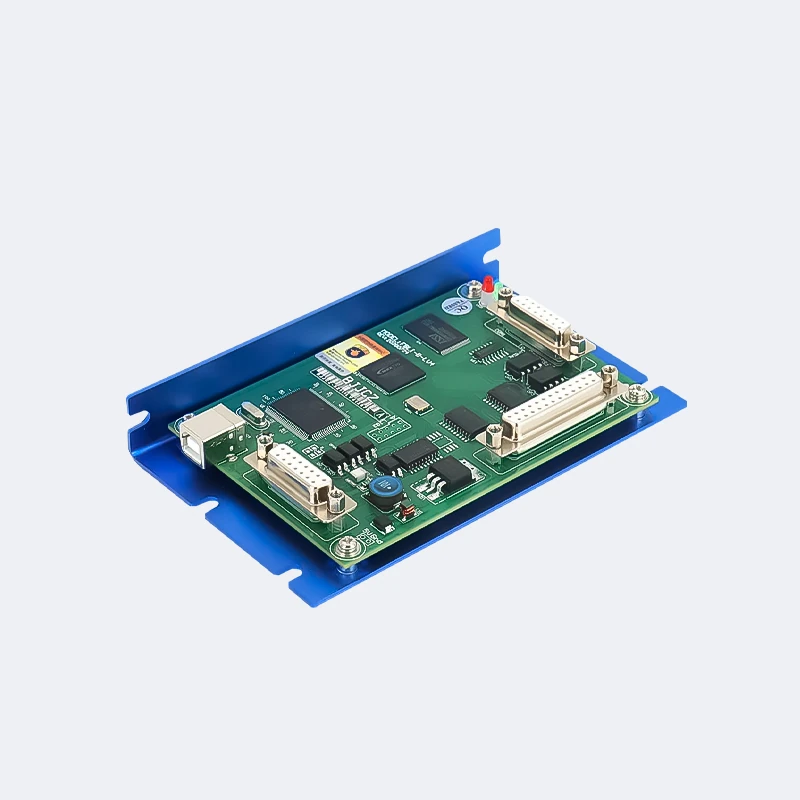
| Controller / software | JCZ / EZCAD2; exact board and software confirmed |
| Cooling | Air cooling; final source requirements govern |
The values below identify this product and its listed options. The selected source, optics, controller, accessories and site utilities must be named in the quotation. Motion speed and positioning figures do not establish finished-part tolerance or production throughput.
Materials and process limits
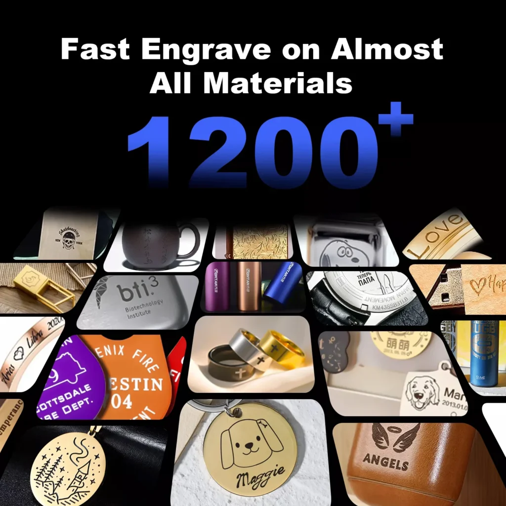
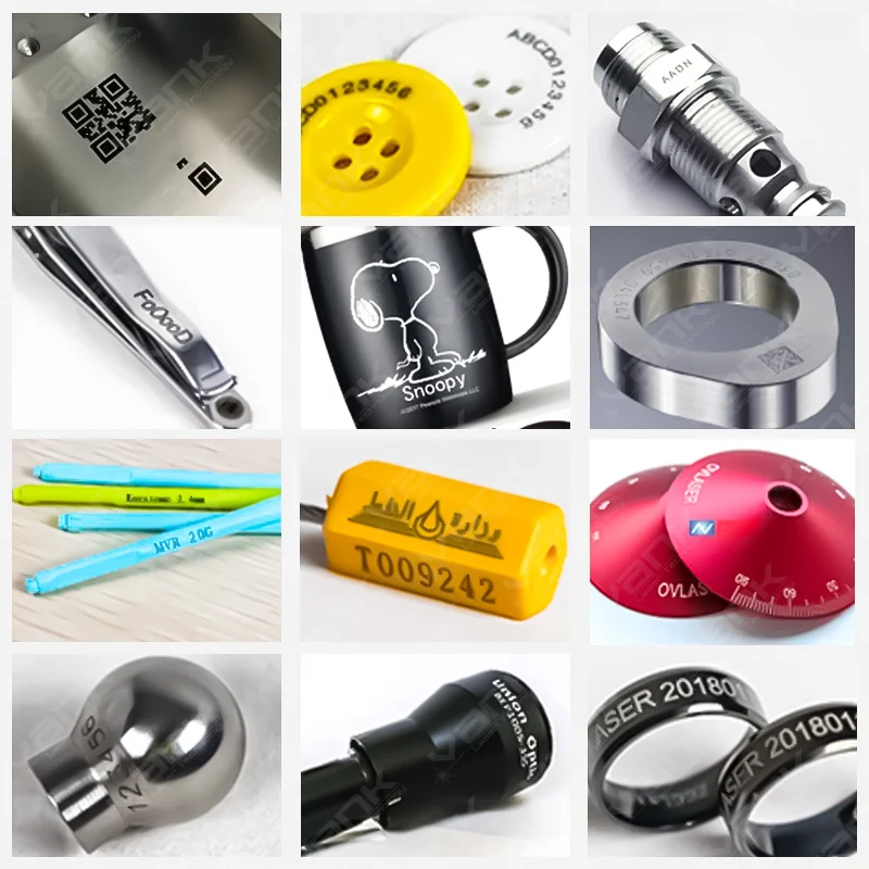
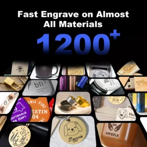
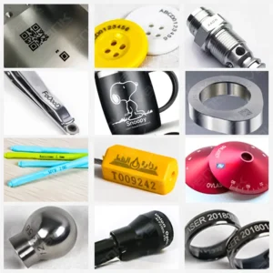
The 1064 nm fiber process is mainly used for stainless steel, carbon steel, aluminum, brass, copper, titanium, precious metals and compatible coatings. Some engineering plastics mark well after testing. Glass, clear acrylic, wood, leather, fabric and stone usually need a UV or CO2 machine. Plating, pigments and heat-sensitive inserts can change the result.
Production workflow
Import text, logos, serial data, QR or Data Matrix codes and compatible vector or bitmap files in the supplied software. Set the fixture, focus and field correction, then qualify a recipe on the part. EZCAD2 and LightBurn are not interchangeable on every controller; confirm the installed board, driver, source protocol and license before choosing software.
Options to specify
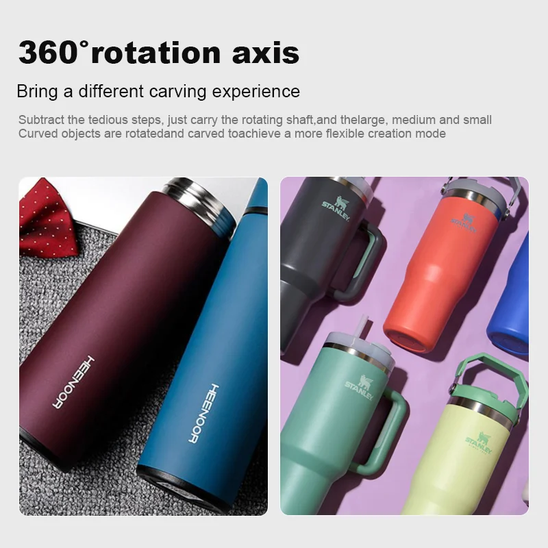
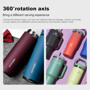
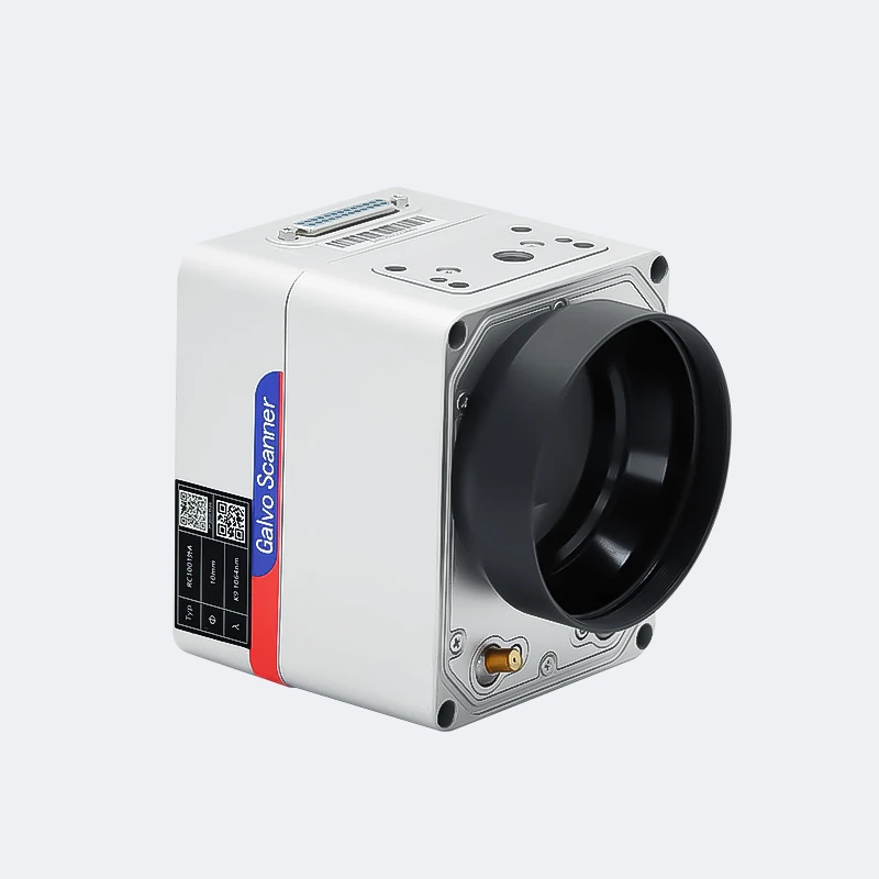
Select Q-switched or MOPA by the required contrast, depth and heat input. A larger field lens changes spot size and working distance. Rotary fixtures require the part diameter, weight and available Z clearance; autofocus and 3D scanning are separate options. Open workstations require a controlled laser area or a suitable enclosure and extraction.
Plan suitable guarding, interlocks, emergency stops, extraction and operator training for the supplied laser system. The finished machine classification must be verified; an enclosure alone is not proof of Class 1 compliance. Follow the supplied operating and maintenance instructions.
Sample test and acceptance
Approve a representative sample and the written configuration before ordering. Record the material, source, settings, lens or nozzle, fixture, appearance, dimensions and complete cycle time. Keep those results as the production acceptance reference.
Deep engraving and color marking
Deep engraving and color marking require a defined material and process test. Depth depends on source, lens, passes, hatch and permitted cycle time. Color effects depend on alloy, surface and pulse control and are not a universal feature of every fiber source. Specify measured depth, appearance and durability as acceptance criteria.
Installation, service and documentation
Ask Vank Laser to include the machine layout, electrical requirements, supplied software, operating instructions, maintenance schedule and recommended spare parts in the technical proposal. Agree commissioning, operator training, support language, warranty coverage and service responsibilities before shipment. Request conformity documents for the actual machine and destination.
Request a sample test and quotation
Send the alloy or polymer grade, coating, part dimensions, marking area, artwork, smallest code, contrast or depth target, cycle time and fixture needs.
Send the destination country, installation voltage and required delivery scope with your inquiry. Ask for sample photos or video, measured results and a configuration-specific quotation.
Request a sample test and configuration quote
Compare related machines
Machine and component photos
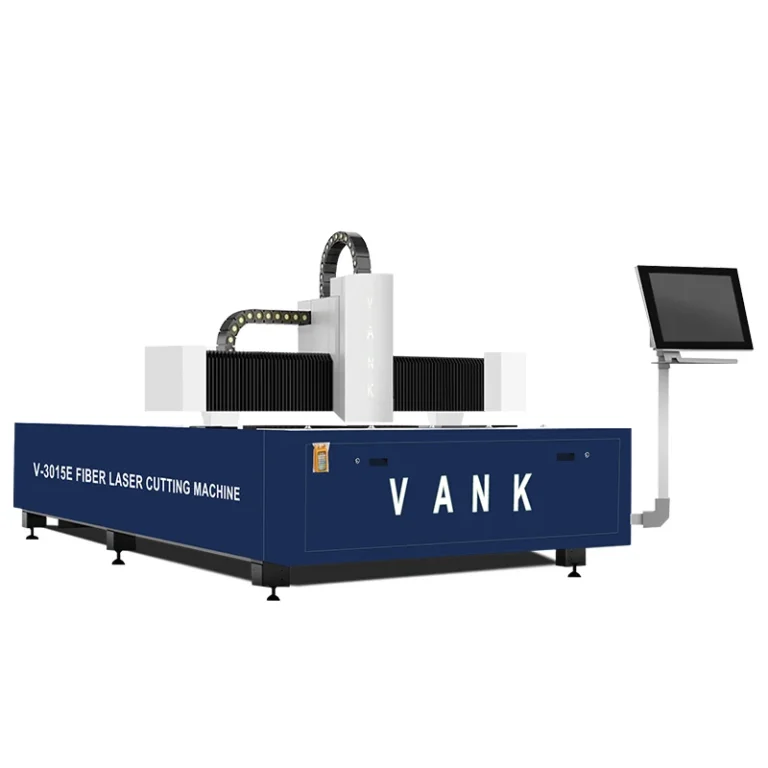
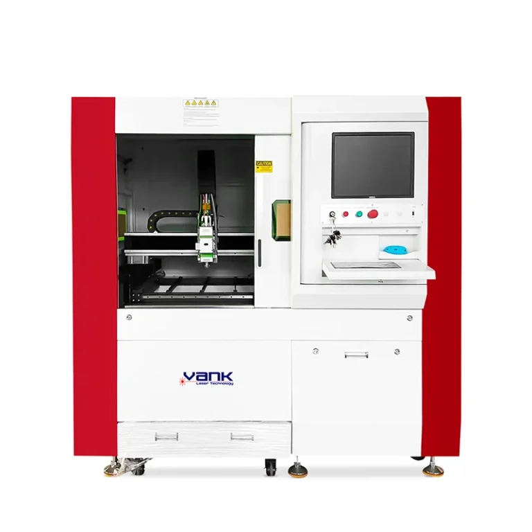
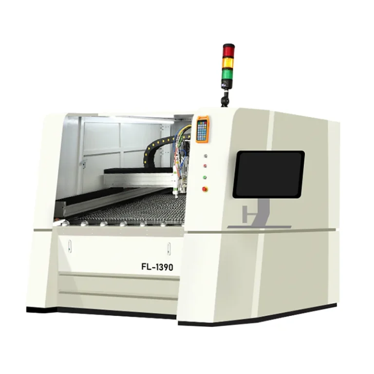
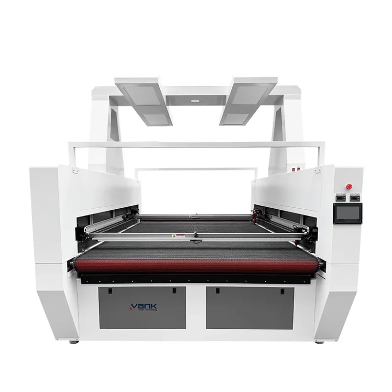
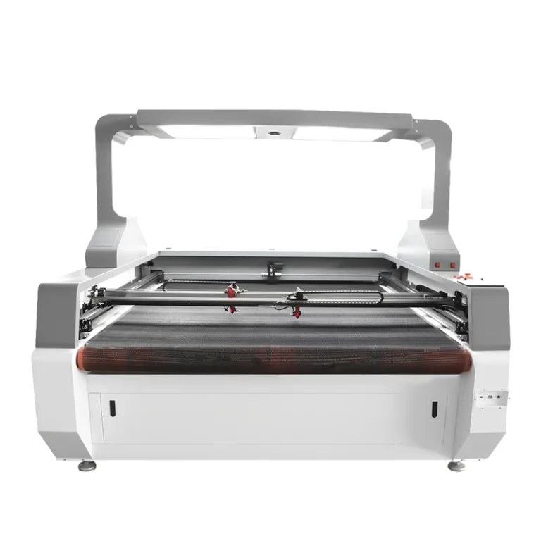
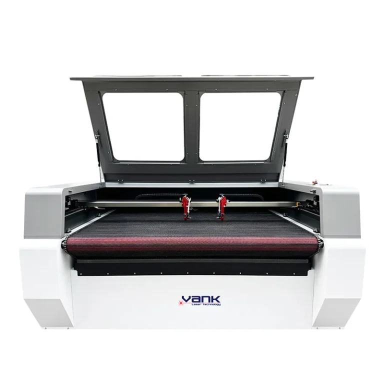
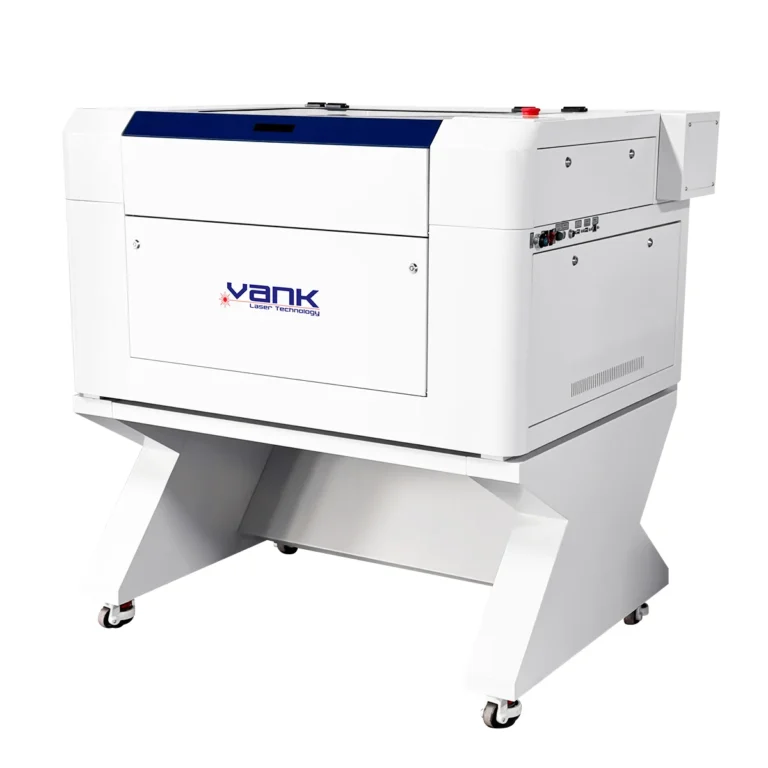
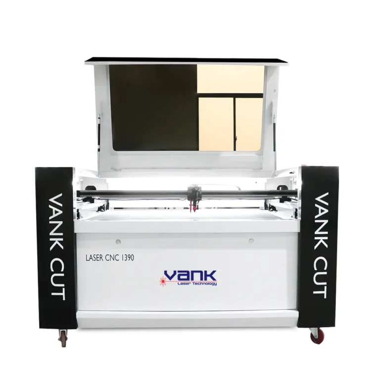
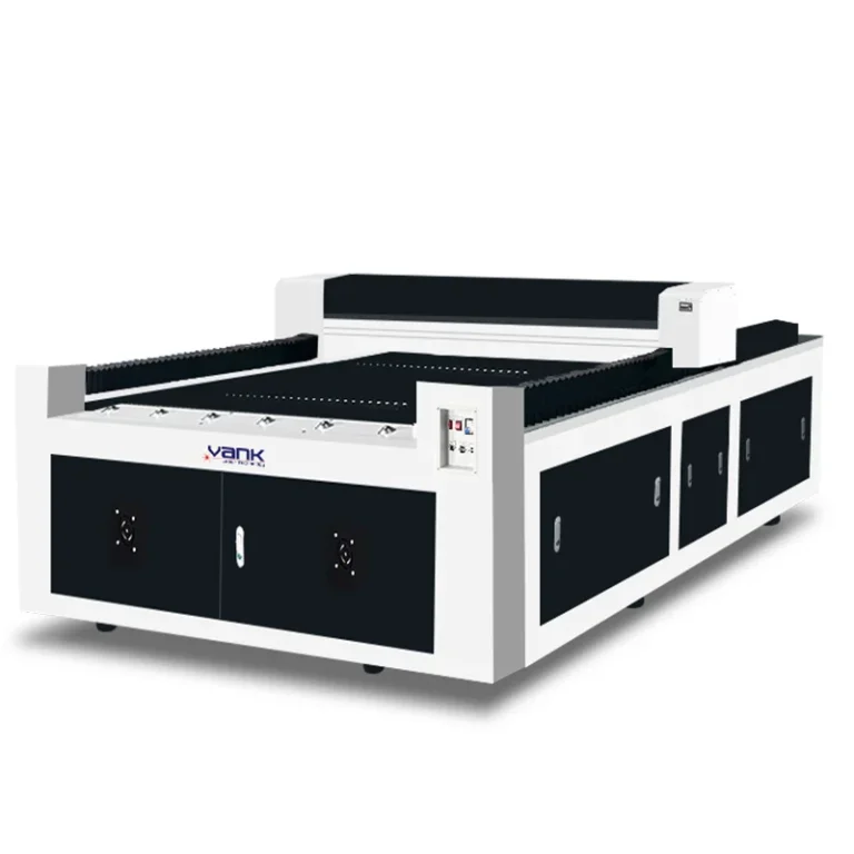
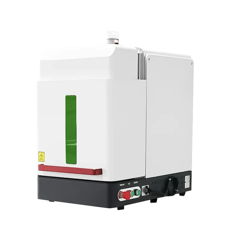
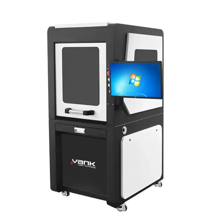
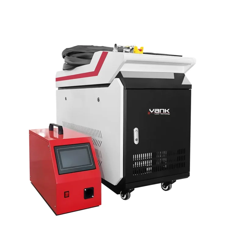
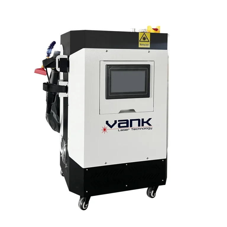
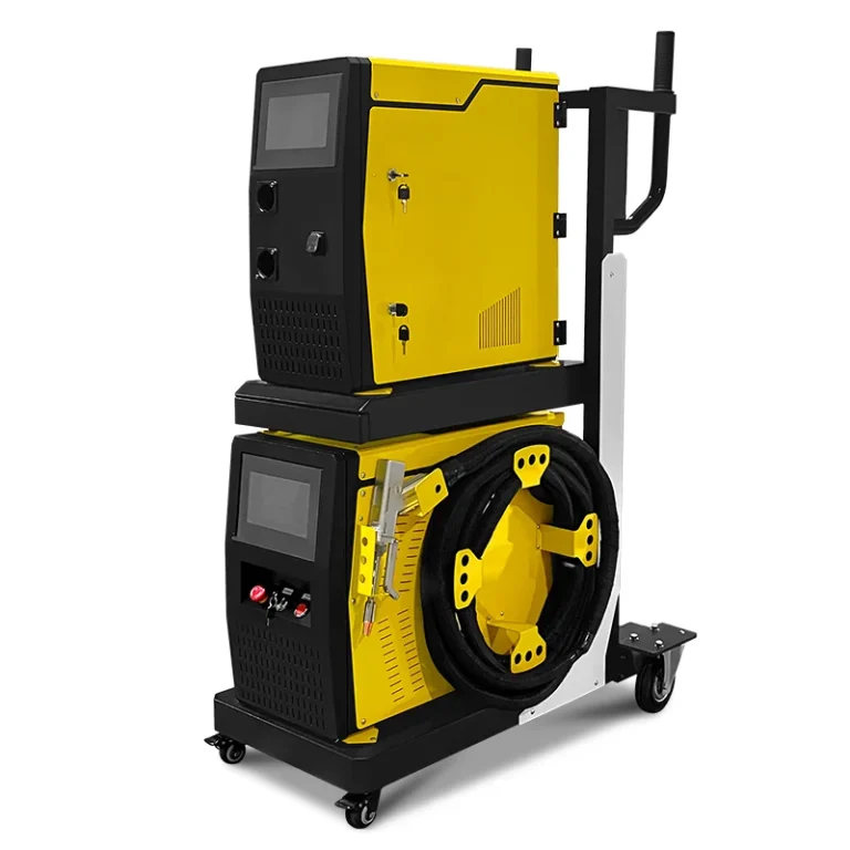
Photos illustrate the product or component family. Included brands, accessories and configuration are defined in the approved quotation.
Product videos
Vank product-family demonstration. The machine shown may have a different power or optional equipment; confirm the configuration for your order.